Technical guide for window-treatment professionals
Roller Shade Tube and Motor Matching: Diameter, Adapters and Torque
Tube outside diameter alone does not establish motor compatibility. The internal profile, crown and drive adapters, idler, bracket interface, load and electrical configuration all need to match. A motor that slides inside a tube is only the beginning of the fit review.
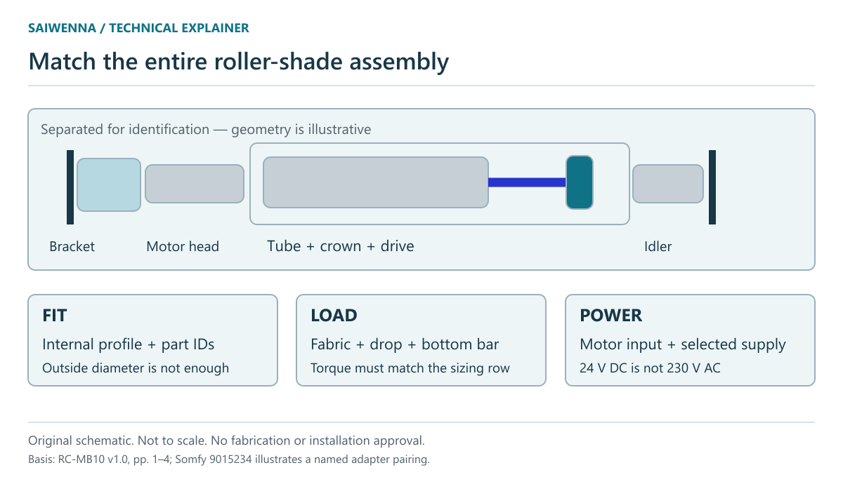
Use a matching chain, not one diameter
| Interface | Identity to record | Reason |
|---|---|---|
| Motor to tube | Exact motor model and body size; tube section and internal profile | Similar outside diameters can conceal different internal geometry |
| Crown and drive | Part references and manufacturer-approved tube/motor pairing | The selected drive must transmit rotation through the intended interface |
| Idler and brackets | Idler/end-cap identity, motor-head attachment and bracket type | Both ends must fit the selected tube and mounting arrangement |
| Load and travel | Fabric, finished dimensions, bottom bar and approved sizing basis | Physical fit does not establish lifting capacity |
| Power and controls | Motor input, supply output and documented command interface | A mechanical adapter does not change voltage or protocol |
Somfy’s 9015234 accessory page is a useful example of an explicitly named motor-family/tube pairing: its crown and drive set is described for specified Somfy motors and a RollEase 2.5-inch tube. That reference illustrates the level of identity needed. It is not evidence of compatibility with RC-MB10 or Motionblinds.
What the RC-MB10 reference actually shows
| Tube row | Documented width × height | Operation / torque reference |
|---|---|---|
| 38 mm | 2300 × 3200 mm | Manual only |
| 42 mm | 2500 × 3600 mm | Recommended 6 Nm |
| 50 mm | 2600 × 4200 mm | Recommended 6 Nm |
| 65 mm | 3000 × 5500 mm | Recommended 8 Nm |
The RC-MB10 technical sheet, page 1 associates these rows with 300 g/m² fabric. Treat the dimensions and torque entries as conditional reference rows. They do not confirm an order with a different fabric, bottom bar, mounting detail or motor.
The section drawing on page 4 gives 38 mm outside / 36 mm inside for the manual tube and 42 mm outside / 39.5 mm inside for the manual-or-motorized tube. Even an inside-diameter match needs the actual internal profile and adapter drawing. Do not obtain fabrication dimensions by measuring a PDF illustration on screen.
A useful mismatch to catch before purchase
CM-50-E-R is documented as a 24 V DC motor with a maximum 6 Nm torque. The 65 mm RC-MB10 row recommends 8 Nm. Those two facts do not establish that the 65 mm configuration can use CM-50-E-R at the row’s stated size. Ask for a confirmed alternative configuration or revised size/load review.
The same reference separately lists CM-10-QC at 8 Nm, with a 230 V AC / 50 Hz input. Matching that torque number does not make it a substitute for the 24 V motor or establish suitability for a US/Canada mains supply. Keep the power architecture and destination-market evidence as separate decisions.
The CM-50-E-R manufacturer manual retains the wording “Indoor and household use only.” Project-use decisions must preserve that restriction in the technical review. Neither the motor reference nor the adapter example establishes complete-system UL/ETL/FCC certification.
Check the assembled roll and service space
Tube size is not the maximum diameter of fabric wound around the tube. Fabric thickness, drop and attachment details affect the finished roll envelope. The RC-MB10 drawing identifies M and L bracket configurations with roll-diameter references of 85 mm and 120 mm and installation-space references of at least 100 × 100 mm and 140 × 140 mm. These values belong to those documented configurations.
Record the maximum assembled roll, bracket fixing access and motor removal path on the section. Use roller-shade pocket planning for the surrounding ceiling coordination. Leave project-specific clearances open until the selected assembly is reviewed.
Make the supplier’s answer comparable
Send one configuration record per distinct shade type: opening ID, finished width/drop, fabric code and mass, tube drawing, motor model, crown/drive and idler references, bracket arrangement, input supply, control requirement and drawing revision. Ask the supplier to return a confirmed bill of materials and the sizing basis, rather than a statement that the parts are “compatible.”
The roller-shade technical pack provides the existing reference download and project inputs. Continue to motorized roller shade systems when the requested application and component identities are ready for review.
Related technical decision: Standard Roll vs Reverse Roll: Roller Shade Clearance and Light Paths.