SAIWENNA / CONTROL ENGINEERING
Dry-Contact Shade Control Modes: Hold-to-Run, Pulse and Stop
A dry-contact input name does not define what the shade does after the contact opens. Before selecting a relay panel or controller, record the command behavior supported by the exact motor and the configured mode. The useful deliverable is a command-and-response record, not a guessed terminal diagram.
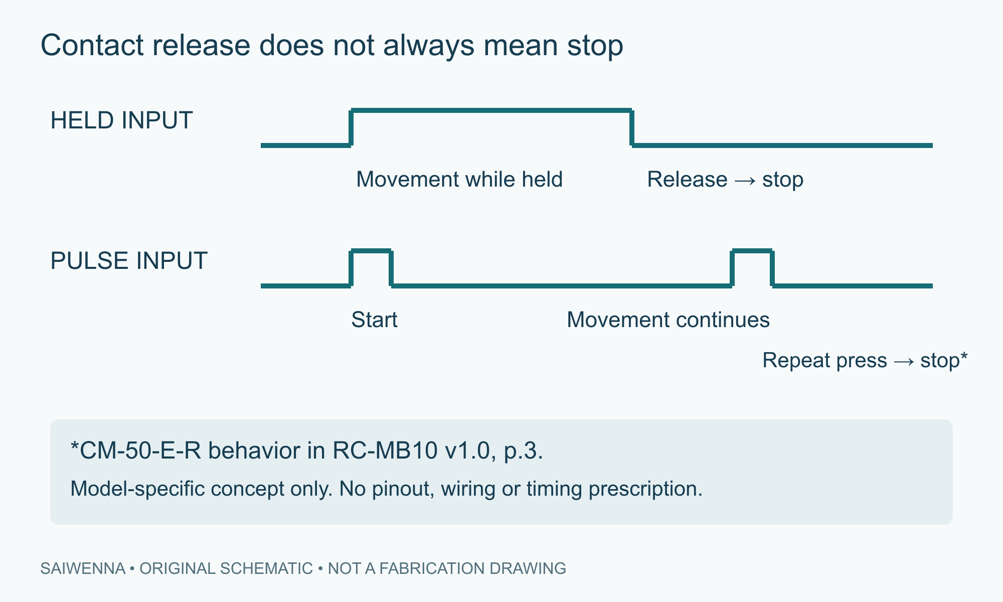
Read the command sequence
The following behavior descriptions come from the CM-50-E-R section of Saiwenna’s RC-MB10 v1.0 technical reference, page 3. They describe that reference, not every dry-contact motor. The current motor revision, manufacturer instructions and configured mode still need to match.
| Reference mode | Input behavior | Expected response in that reference | Question for the integrator |
|---|---|---|---|
| Hold-to-run (documented default) | Direction contact remains held, then releases | Movement while held; stop on release | Does the output remain asserted for the required period? |
| Pulse | A short press, followed by another during travel | First press operates; another press during travel stops | Is the pulse duration accepted, and which repeat command stops? |
| Pulse with Stop | Directional pulse and a separate Stop input | Pulse operation with a separate stopping command | Is the separate Stop command available and mapped? |
| Single button | Successive commands on one button | Sequence cycles through open, stop and close | Can the controller track the required sequence and recover predictably? |
A controller configured to send only a brief pulse may produce unexpected behavior when the motor expects a held input. Conversely, a maintained output is not a substitute for a documented pulse or Stop sequence. Confirm the supported timing from the selected equipment; this guide does not prescribe a universal pulse width.
Use this acceptance record before releasing the controls scope
Print or copy the following fields. A qualified installer or integrator performs any powered testing using the manufacturer’s complete instructions and a safe test setup.
- Identity
- Motor model ______ Hardware/firmware ______ Manual/revision ______
- Interface
- Controller and output model ______ Input ratings/source document ______
- Configuration
- Mode selected ______ How verified ______ Date/person ______
- Command 1
- Input action and duration ______ Expected movement ______ Observed ______
- Release
- Expected behavior when contact opens ______ Observed ______
- Stop
- Documented stopping action ______ Observed ______
- Repeat or reverse
- Permitted sequence/interlock ______ Expected ______ Observed ______
- Interruption and recovery
- Approved power/communication recovery test ______ Result ______
- Decision
- Accepted configuration ______ Unresolved items ______ Release owner ______
A successful local switch test establishes only that tested path. Repeat the agreed command sequence through the actual automation path before accepting an end-to-end integration. Keep command success separate from verified shade-position feedback.
Send the missing interface facts, not a protocol label alone
For a technical review, include the model/revision, controller, intended commands, required feedback, selected mode and unresolved acceptance fields. State who owns electrical design, interface configuration and commissioning. If a behavior is undocumented, leave it unresolved until the relevant supplier confirms it.
Use the motor and control matrix
Related: KNX, RS485 and dry contact · BMS responsibility boundaries · Send control-coordination requirements.
Sources and scope
- RC-MB10 Technical Data Sheet v1.0, 10 September 2026, pp.2–3
- Motionblinds CM-50-E-R user manual, printed p.13 safety statement
Technical reference reviewed 20 October 2026. Manufacturer examples retain their own product scope. Final supply, pricing, lead time and project suitability require configuration-specific confirmation.