Technical guide for window-treatment professionals
Motorized Shade Speed: RPM, Curtain Travel and Opening Time
Motor rpm measures revolutions per minute. Curtain travel speed measures distance per second. Neither number alone establishes how long a complete installed shade takes to open. The transmission, winding diameter, travel distance and start/stop behaviour matter.
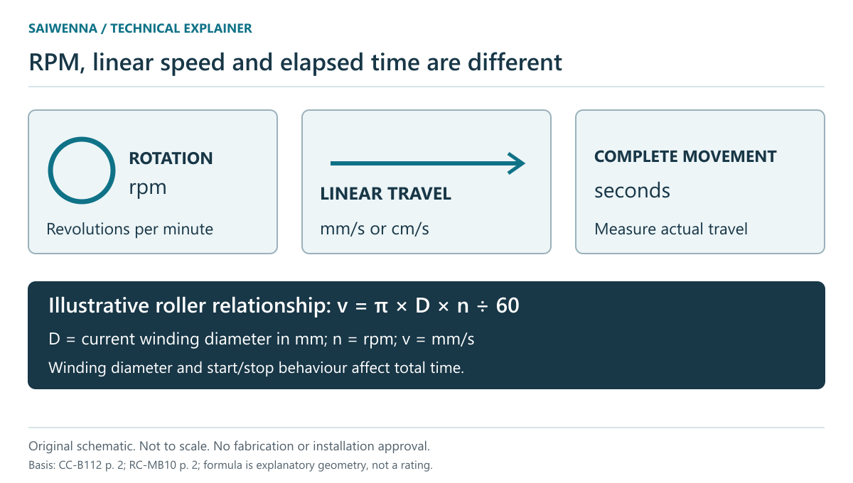
Read the unit before comparing the number
| Reference | Documented speed | Correct interpretation |
|---|---|---|
| CM-51-E / CC-B112 | 13 cm/s curtain travel; 100 rpm shaft speed | Two different quantities in the same source table |
| CM-50-E-R / RC-MB10 | 16 / 20 / 24 rpm; 20 rpm factory default | Motor speed settings, not fabric travel in cm/s |
| CM-10-QC / RC-MB10 | 15 rpm | A separate 230 V AC / 50 Hz motor reference |
The CC-B112 sheet, page 2 and RC-MB10 sheet, page 2 are the source for these values. Do not compare 100 rpm with 13 cm/s as if one is a faster version of the other. The sheet does not state an adjustable-speed choice for CM-51-E.
For a roller, diameter links rotation and fabric travel
In a simple no-slip winding model, one revolution moves a length of fabric approximately equal to the circumference at the current winding surface. If effective diameter D is in millimetres and speed n is in rpm, the instantaneous estimate is v = π × D × n ÷ 60, in mm/s.
| Hypothetical effective diameter | Hypothetical speed | Calculated instantaneous travel |
|---|---|---|
| 50 mm | 20 rpm | 52.4 mm/s |
| 80 mm | 20 rpm | 83.8 mm/s |
These are arithmetic examples, not RC-MB10 configuration ratings. Effective winding diameter includes the material already on the roller; it is not necessarily the bare tube diameter. As fabric winds on or off, that diameter changes. A constant-rpm motor therefore need not produce constant fabric-edge speed.
Fabric thickness, bottom attachment, selected motor behaviour and end-limit ramping all affect a complete travel-time observation. The simple formula is useful for identifying missing information, not for guaranteeing a delivery specification.
For a curtain track, use the distance the carrier actually travels
At a hypothetical constant 13 cm/s, a 1.5 m carrier journey takes about 11.5 seconds before allowing for acceleration, deceleration or other effects. The calculation is 150 cm ÷ 13 cm/s. It is not a measured CC-B112 opening time.
On a centre-opening arrangement, the movement of each leading carrier is not automatically the full track length. On a one-way draw, the journey and parked fabric differ. Measure the relevant carrier path from the approved layout, including the selected meet/overlap arrangement, before calculating or observing timing.
Motor duty limits are a different specification
Continuous-operation limits describe the permitted operating interval in the applicable documentation, not the time to open one window. The references list 12 minutes for CM-51-E and CM-50-E-R, and 4 minutes for CM-10-QC. Do not turn these entries into a repeated-cycle life claim or assume a cooldown interval that the source has not provided.
As a separate manufacturer example, Crestron’s CSM(I)-QMTDC-163-1-SG specification lists speed and duty cycle in distinct rows. Its values and conditions belong to that Crestron product; they do not change the Motionblinds references above.
Specify timing as an observation the project team can repeat
Record opening ID, motor model, speed setting where supported, fabric/track configuration, start and end positions, trigger method and the observed elapsed time. For grouped shades, distinguish command-response delay from travel speed and final alignment. A common group command does not prove identical mechanical motion.
Use a representative commissioned assembly and agree the acceptance method before quoting a timing tolerance. Continue with the site commissioning checklist and control coordination guide. For roller component identity, see the tube and motor matching guide.