Metro-Related Facade Reference
Qingdao Metro Blue Silicon Valley Line Adjustable Aluminum Louver Reference
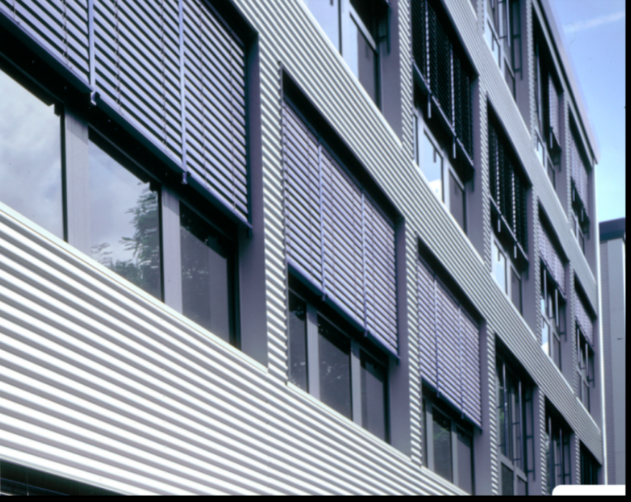
This completed Qingdao Metro Blue Silicon Valley Line reference documents motorized adjustable aluminum louvers. The supplier portfolio classifies the project within its real-estate category, reports an approximate 5,800 m² shading scope and shows the system across repeated facade openings.
Completed supplier-network reference
This is a completed manufacturing-network project reference. It documents work delivered by a specialized engineering and manufacturing resource within Saiwenna’s current supply network; it is not presented as a Saiwenna-contracted project.
Qingdao, China
Real estate; metro-related building and facade reference
Completed supplier-network reference
Motorized adjustable aluminum louvers
Approximately 5,800 m² in the supplier portfolio
Not stated; no inference made
Documented Scope
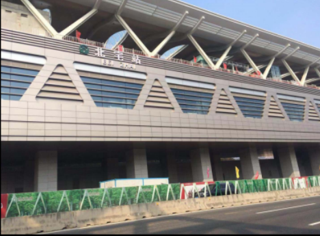
The portfolio identifies motorized adjustable aluminum louvers and reports an approximate 5,800 m² scope. The images show both metro-related building context and a closer facade view. No wind class, fire rating, motor specification, control protocol or project year is published.
System Direction
The reference is an adjustable louver facade application. It should not be confused with the site’s motorized aluminum skylight shutters, which address roof openings and different system geometry. Final product selection depends on the actual facade and project requirements.
Engineering Challenge
Long elevations and repeated bays require consistent blade alignment, support, drive planning and access. Large facade projects also need clear responsibility boundaries among the facade, shading, electrical and control teams so that adjustment, inspection and maintenance can be carried out safely.
Configuration Review
The design review should distinguish fixed facade elements from the adjustable louver assembly and identify each operating zone. Blade span, orientation, support, drive arrangement and access all depend on the approved facade geometry. Corners, changes in elevation and non-standard bays should be scheduled separately instead of being assumed to match a typical module.
The historical images show an installed direction but do not publish the engineering calculations or performance classification. Those items belong to the selected configuration and applicable project standard.
Facade and Installation Interface
For a new project, the design team should provide elevation geometry, bay dimensions, support conditions, fixing zones, blade direction, operating intent and service access. Wind, load, durability and other performance requirements must be confirmed for the selected configuration and applicable project standard.
Commercial Package and Site Sequence
A quotation should separate louver modules, motors or drives, control components, supports, accessories, packing and installation scope. The site sequence should confirm when the supporting facade is ready, how final dimensions are approved and how the system will be protected before commissioning.
Inspection and Handover
For repeated motorized zones, the project team should agree on identification, operating checks, alignment criteria and responsibility for final adjustment. Spare strategy, operating instructions and fault reporting should reflect the selected system rather than a generic blind checklist. A facade mock-up can also confirm appearance, movement, access and interface assumptions before full release.
Why This Reference Matters
This project adds exterior adjustable-louver evidence and a metro-related facade application to the portfolio. It proves a materially different application from curtains, interior roller blinds and architectural fabric roof systems.
For architects, facade contractors and project buyers, the value is the visible repeated-bay application and source-reported scale. It provides a grounded starting point for a new engineering review without transferring unverified performance values from one building to another.
What Must Be Confirmed for a New Louver Project
- Elevation schedule, bay dimensions and support structure.
- Louver orientation, adjustment range and operating sequence.
- Motor, drive, power and control direction.
- Fixing, access, drainage and maintenance responsibilities.
- Project-specific wind, load and compliance requirements.
Project Gallery
Planning a Similar Project?
Send the project location, drawings or opening schedule, system direction, installation interface and control requirements. Saiwenna will coordinate a configuration review with the relevant engineering resource.